Meshing Toolbox in FEMAP
Quickly and interactively edit geometry and create quality mesh using the Femap Meshing Toolbox
The Meshing Toolbox is a centralized collection of FEMAP's geometry clean-up and meshing functionalities in a single pane. Below you will find an overview and demonstration of the included tools:
Geometry Editing Tabs
- Feature Suppression
- Feature Removal
- Feature Editing
- Geometry Editing
- Combined/Composite Curves
- Combined/Boundary Surfaces
Meshing Tabs
- Mesh Sizing
- Mesh Surface
- Mesh Locate
- Surface Mesh Quality
Geometry Editing Tabs
Feature Suppression
Feature Suppression allows you to suppress loops, curves, and surfaces. Suppressed geometry still exists in the model and can be restored at any time.
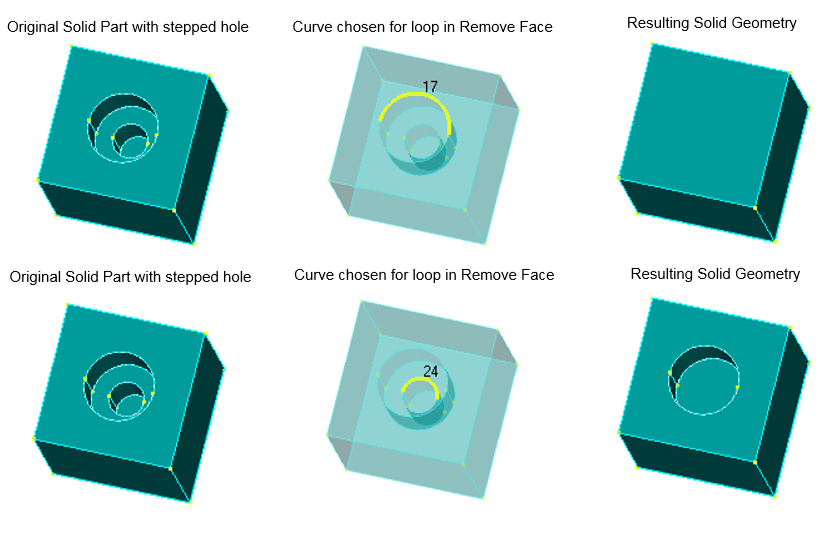
Feature Removal
This tool aggregates Femap commands that permanently remove geometric entities, such as removing loops, surfaces, and curves.
In the case of “Aggressive Removal”, localized geometry around the selected curve may be slightly altered to accommodate the curve no longer being part of the geometry.
Feature Editing
This tool is used to make relatively basic alterations to Geometric “features”. Examples include modifying the position of a hole, boss, or rib, changing the length/width of an extension or entire part, revolving a face to create an angled wall, or extending a revolved body, etc.
Different operations require using the different Surface Selection Methods to select appropriate surfaces to be successful. Also, specifying a “realistic” translation or rotation vector is required.
Geometry Editing
Powerful geometry editing tools including:
- Operation – Determines which operation will be used to “split” or modify a curve or surface.
- Curve Break – Specificy a “Location to Break At” by entering XYZ coordinates or click the icon button to use the standard Coordinate Locate dialog box, then choose a curve to break.
- Point to Point – Select one point on a surface, then a second point on the same surface to create a line which splits the surface.
- Point to Edge – Select one point on a surface, then an edge/curve on the same surface to create the shortest possible straight line from the point of the edge which will “split” the surface.
- Edge to Edge – Select one edge/curve on a surface, then another edge on the surface. Lines, which follow the surface, will be created from the endpoints.
- Pad – Breaks the surface geometry surrounding a hole into four map-meshable regions.
- Washer – Uses offset curves to create map-meshable regions around holes.
- Extend – Extends the curve or surface to the point you designate.
- Project/Move Point – Projects a point or points used by a surface, solid, sheet solid, or general body onto an entity of the selected type.
- Project Curve – Creates a new curve or curves on the selected surface using a normal projection.
Combined/Composite Curves | Combined/Boundary Surfaces
Curves
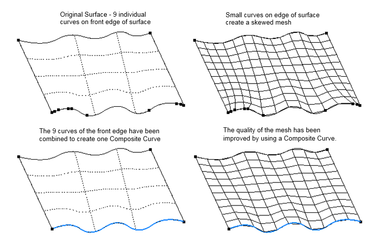
In some cases, combining several smaller curves along the edge of a surface will allow you to create a higher quality mesh on the surface. This tool allows you to combine curves by choosing the curves themselves or a point that two curves share.
A “composite curve” will be created in FEMAP, which will be used for mesh sizing purposes instead of the underlying curves. There are also options for splitting a composite curve at a selected point or removing any of the underlying curves.
Surfaces
You may want to combine several surfaces into a “boundary surface”, such as when there are sliver surfaces next to a much larger surface. By combining the selected surfaces into one boundary surface, all of the internal curves can be ignored during the meshing process.
Boundary surfaces can be created by selecting a curve shared by multiple surfaces or choosing the surfaces themselves. Also, any underlying surface can be removed from a boundary surface or split along a curve.
Meshing Tabs
Mesh Sizing
Modify mesh sizes on curves via setting, increasing, or decreasing the mesh size on selected curves, and includes the ability to match mesh sizes with other curves.
Mesh Surface
Mesh surfaces through free or mapped meshing with triangular or quad surface elements. Allows surfaces to be meshed or remeshed “on-the-fly” using various surface meshing methods, options, and/or mesh approaches.
Mesh Locate & Mesh Quality
Mesh Locate
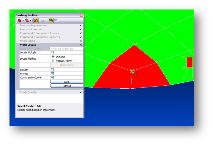
There may be times when you would like to make small changes to an existing mesh simply by moving one or several nodes without changing the number of elements. This tool will allow you to do that while making sure that, as you move the node or nodes dynamically, they remain attached to specified solids, surfaces, and curves. If you have no geometry, it will follow the overall topology of the selected standalone mesh.
There are also options to move the selected nodes by a defined amount, continually smooth the mesh as the nodes are moved, and allow the moved nodes to no longer be attached to surfaces or curves.
Mesh Quality
When the Mesh Quality Toggle in the Meshing Toolbox is set to “on”, this tool allows you to graphically see an element quality value plotted on each element similar to a contour/criteria plot.
There are several different element quality types which can be selected and each type has default automatic values, but user-defined values can also be specified. Also, the minimum and maximum quality values for the specified “quality type” are listed in the bottom fields.
Other checks available in Femap allow you to verify:
- There are no discontinuities in the model by viewing free edges and faces – something that cannot be checked just by looking at the model
- Check coincident elements and nodes which can also be indicators of discontinuities
- Load checking by summing forces
- Mass property checking
Related Articles
The Meshing Toolbox
10 Tools to Quickly Create and Refine Accurate Finite Element Models This deep-dive into the meshing toolbox will showcase tools that will help you edit geometry and create accurate meshes from the associated geometry. This webinar will explore all ...Manipulating Geometry and Meshing in FEMAP
This tutorial demonstrates how quickly FEMAP can modify geometry and create finite element models using the Meshing Toolbox, and Mid-surfacing and Non-Manifold Add tools Tutorial Overview This demonstration will show how quickly FEMAP can modify ...Part 4 - Meshing and Analysis Preparation
Introduction Welcome to the introduction to FEMAP video series. In the previous video we set up the material and element properties on the machined arm components and defined loads and boundary conditions. In this video we will continue the ...Whats New In Simcenter Femap 2020.2?
What is in this webinar? SDA Stress Engineer Glenn Andrew presents this webinar on What's New In Simcenter Femap version 2020.2. During this webinar you will learn about some of the new changes in the latest version of Simcenter Femap including: UI ...Part 1 - Femap User Interface
Introduction Before we begin our analysis, let's get familiar with Femap’s user interface. User Interface We’ll look at the main components of the user interface, including the maps command interface, graphics windows, and tabbed and dockable panes. ...